Natural gas provides clean, reliable, and cost-effective energy to people all around the world. Natural gas is a cryogen, which implies that at extremely low temperatures it is a liquid. Natural gas may be transported as a liquid from locations with abundant supply to areas with high demand in an efficient and safe manner.
LNG storage tank systems keep the gas in a liquid state for storage or transmission. These tank systems are meticulously designed and well-built. In LNG storage systems, auto-refrigeration is employed to maintain constant pressure and temperature in the tank. This method is, in reality, quite old. West Virginia built the first natural gas liquefaction plant in 1917. Many advancements have been made since then to increase natural gas storage, but the systems continue to function in the same way. Here’s what we need to know before designing and constructing an LNG storage system.
API Standards and Codes
In the 1960s, the American Petroleum Institute (API) established rules for the design, construction, and material selection of storage tank systems. These standards contribute to the overall safety and quality of the industry. API codes are also continually updated to reflect industry innovations and best practices.
Types of LNG Storage Tanks
Liquefied gas storage tanks are classed based on their kind and size using a range of standards and guidelines that differ in terms of when they were published and the quantity of information they give. The wording used by the two German standards, DIN EN 1473 and DIN EN 14620, is even diametrically opposite. This section will utilize either the vocabulary from the British equivalent, BS EN 1473, or the nomenclature from API 625. API 625’s British counterpart is BS EN 1473. From a practical sense, the phrase “containment tank system,” as used in API 625, seems to be the most appropriate, since the multiple, yet coordinated, components interact to create a cohesive system. Containment tank systems are categorized as single, double, or complete according to the standards EEMUA, BS 7777, EN 1473, EN 14620-1, NFPA 59A, and API 625. The membrane tank is an extra tank type that is detailed in further detail in the European standards EN 1473 and EN 14620.
Until the 1970s, the only kind of tank built was the single-wall tank. The hazard scenarios that resulted from abnormal actions such as inner tank failure, fire, blast pressure wave, and impact inspired the subsequent further development of the various types of tanks or tank systems, as well as the associated requirements placed on the materials and construction details. Because of the threats that a tank failure brings to the surrounding areas, it is essential to choose the proper kind of tank system.
The repercussions of a failure of the inner container on the tank as a whole and its surroundings for three commonly used tank systems will be shown utilizing the failure of the inner container. The evolution of these three tank systems will also be studied.
System with a single containment tank

A container that is both liquid and vapor tight is referred to as a single containment tank system. It may be built as a single-wall, liquid- and vapor-tight structure, or as a combination of inner and outside containers. In the latter case, the inner container is open at the top and liquid tight. When an outside container is used, it is largely to enclose the insulation and protect it from moisture, as well as to accommodate the gas vapor overpressure. It is not designed or intended to store LNG that has spilled from the tank. If there is just one containment tank, it must be surrounded by some form of safety barrier, usually an earth embankment, to prevent the liquid from escaping uncontrolled and causing damage.
The inside container of an EN 14620 container must be made of steel, but API 625 permits for the use of prestressed concrete in some situations. If you use an outside container, it is normally made of carbon steel to keep the elements out.
System with two separate containment tanks
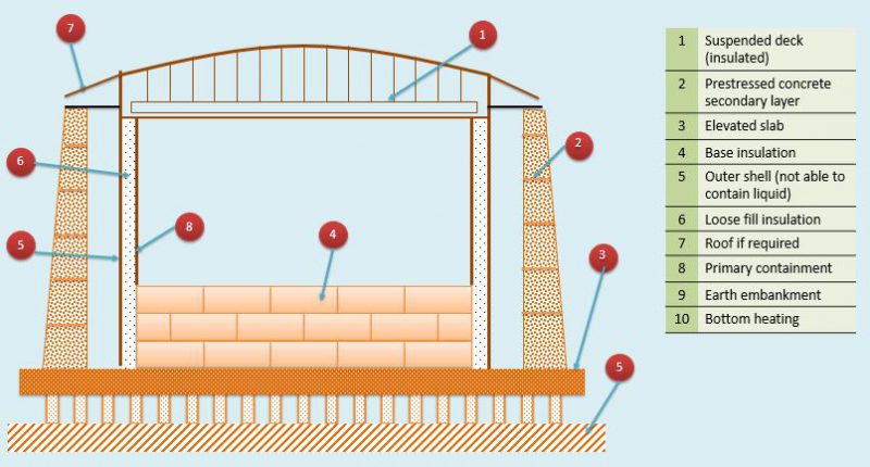
Double containment tank systems are made up of a liquid- and vapor-tight primary container that satisfies the criteria for a single containment tank system but is contained within a secondary container that fits the criteria for a double containment tank system (Fig. 4.2). In the event of a leak, it is intended to be open at the top and capable of capturing any liquefied gas that escapes. On the other hand, it is not meant to obstruct gas escape. In order for the primary and secondary containers to operate effectively, no more than 6 m must be left between them. According to API 625, both steel and prestressed concrete are permissible materials for both containers.
System with a Complete Containment Tank
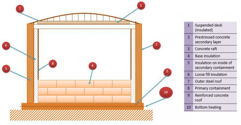
A complete containment tank system is made up of primary and secondary storage containers that work together to provide a comprehensive and integrated storage system. The primary container is a cylindrical steel tank with a single self-supporting and self-contained shell. Alternatively, it might be open at the top, rendering it incapable of holding any vapors, or it could be built with a dome roof, preventing vapor from escaping in such a case.
The secondary container must be a self-supporting tank made of steel or concrete with a dome roof in order to qualify. If the main container is open at the top, the secondary container must function as the primary vapor containment for the tank during normal operation. In the case of a leak from the primary container, the secondary container must be capable of storing the liquefied gas and remaining liquid-tight while also functioning as the primary vapor containment structure. It is permissible to vent in a regulated way using the pressure release mechanism. API 625 states that “product losses due to permeability of the concrete are permitted” when the outer container is made of concrete. According to API 625, both steel and prestressed concrete are permissible materials for both containers. The existence of vapor-tightness is required for normal operation. Figure 4.3 displays a number of various design options, one of which incorporates a prestressed concrete inner tank.
The standards EN 14620-3 (Annex B) and ACI 376 (Appendix A) specify and illustrate sliding, pinned, and fixed connections between a wall and a foundation slab. Sliding or pinned joints are employed in certain circumstances, however this is only possible in small tanks operating at less severe low temperatures and consequently with less overpressure. Due to the nature of the material, the monolithic wall/base slab connection is the only practical method for LNG tanks.
In order for the system to continue to work properly in the event of inner container failure, the conventional complete containment tank with a concrete outer container and solid monolithic connection between wall and base slab must have two constructional qualities. In such a circumstance, the wall experiences a temperature difference of roughly 100 K and temperature gradients of up to 200 degrees Celsius. With the tank sizes that are commonly employed, this temperature disparity results in a radial shortening of the tank wall of 4–5 cm, depending on the diameter. If no further safeguards are taken at the wall/base slab junction, a failure of the concrete cross-section will occur. One alternative is to build a transition zone at the base of the wall that is at least 5 meters high in order to reduce the contraction of the concrete wall to a level that is commensurate with the surrounding environment. In practice, this is done by including an insulating layer between the base slab and the wall, which comprises a secondary bottom made of nickel steel (9 percent nickel content). The secondary bottom is higher up the wall than the main bottom. Thermal corner protection refers to this section, which is protected with insulation and steel plates (TCP).
This feature protects the insulation while also aiding it in retaining its thermal function, reducing the influence of temperature on the cross-section of the concrete and smoothing the development of deformation. Despite the fact that experience has shown that the risk of a single containment tank failing (assuming it was built in accordance with regulations) is extremely low, such risks can be reduced even further by introducing even stricter requirements regarding material selection, design, construction, inspection, and testing. However, the implications of a tank collapse are so severe for particular hydrocarbon chemicals that an even more complex tank design is necessary to avoid them. The tank system should be chosen with the location, operating conditions, and environmental standards in mind, among other things.
System with Membrane Tank
Only later, in a variety of projects that were extremely distinct from one another, was the membrane system employed for above-ground LNG storage tanks on land. The membrane technology was initially designed for use on LNG tankers and was only subsequently used to above-ground LNG storage tanks on land. In recent years, operators have boosted their demand for membrane tanks as an alternative to 9 percent nickel steel tanks, resulting in a major rise in availability. There are a number of elements that contribute to this. The LNG industry has long attempted to reduce costs by replacing thicker nickel steel plates with thinner stainless-steel plates. This has long been a desire of mine. The advantage of a membrane tank for engineers is that there are no constraints on the thickness of tank wall plates in large-capacity tanks, and the tank has great seismic performance in the event of strong earthquake loads.
Prior to a few years ago, membrane tanks were only available from a few providers, all of whom competed for consumers looking to acquire entire containment tanks. The membrane tank system, on the other hand, was later authorized. Any contractor may now get a license, implying that all suppliers will be able to deliver both entire containment tanks and membrane tanks.
Membrane tank systems, as described in EN 1473 and EN 14620-1, are made up of a thin membrane (which acts as the primary container), thermal insulation, and an outer concrete secondary container, all of which work together to form a composite tank structure. Steel exterior containers are not authorized, according to the guidelines.
The primary container is comprised of a thin stainless-steel membrane that is both liquid and vapor tight and just 1.5 mm thick at its thickest point. Furthermore, the membrane has no load-bearing qualities. The plates are made with corrugations that are 90 degrees apart from one another. Each prefabricated section is screwed or bolted to the outer container. This structure allows the membrane to deform freely in response to heat activities without producing stresses and strains in the membrane. To create a single unit, the separate membrane segments are overlapped and welded together. At the top of the wall, a peripheral plate is utilized to hold the membrane to the concrete wall.
A continuous vapor barrier is attached to the inner face of the tank wall and the concrete foundation slab to prevent any water vapor or water from the concrete from entering the insulation area. This is done to prevent moisture from entering the insulating region. Aside from that, the roof liner, which is composed of plain carbon steel, the compression ring, and the membrane are all welded together to guarantee the tank’s overall gas tightness. This means that both the interior membrane and the outside vapor barrier are sealed, resulting in a sealed insulation region on both the inside and outside. The insulation region is constantly monitored and purged with nitrogen to ensure that the insulation continues to function effectively and to restrict moisture or vapor intrusion.
A secondary membrane is installed within the insulation as an integrated secondary bottom in the foundation slab and the bottom section of the wall, and it is fixed around 5 m up the wall. In the event of membrane failure, it acts as an additional layer of protection for the rigid wall, sheltering it from high constraint loads induced by heat activity. This setup is known as a thermal protection system (TPS). Throughout the structure, prefabricated insulating components are employed.
Given that the concrete outside container is the only load-bearing component of the whole system, it must be capable of withstanding all external loads as well as the loads induced by liquid gas and vapor overpressure. Similarly, during normal operation, a full containment tank system is not exposed to any significant thermal loads. Even if the inner container fails, the concrete exterior tank must remain liquid- and vapor-tight by withstanding the pressure imposed by the liquid and vapor.
Performance Requirements and Design
EN 14620-3 (concrete components) design requirements are quite brief, taking up just one page of the standard. These criteria are focused with establishing the partial safety factors for aberrant activities as well as combinations of abnormal actions. Atypical behaviors that may occur include safe shutdown earthquakes (SSE), explosive overpressure, external impact, and leakage from the inner container (liquid spill).
The design criteria also cover the external container’s liquid-tightness, which is a significant concern. There is a distinction between containers with a liquid-tight steel liner or coating and those without. Assume, for argument’s sake, that LNG is escaping from the inner container and that the inside face of the concrete outer container above the thermal corner protection (TCP) comes into direct contact with the cold liquid, which is at a temperature of 165 degrees Celsius.
As previously indicated, the absence of partial safety factors or combination load factors on the loading side for normal operation and usual activities is an EN 14620 defect that must be addressed by the tank specification in question. When an anomalous action happens, the load case for that action is overlaid on the load cases for permanent and variable actions.
Before closing the outside container, a metallic or polymer liner should be employed to ensure that it is totally vapor- or gas-tight. This is often performed when constructing LNG tanks by joining 5 mm thick standard carbon steel plates to the interior face of the concrete structure. During normal operation, the requirement for vapor-tightness applies.
In the case that the inner container fails, the liquid-tightness condition applies. However, since a conventional carbon steel metallic liner cannot endure cryogenic temperatures, a concrete cross-section must be employed to ensure liquid tightness. The standard only stipulates a residual compression zone of 100 mm in this case, which is far less severe than the requirements of all other related standards.
In the residual compression zone, an additional average compressive stress of 1 N/mm2 (145 psi) is needed, resulting in a residual compressive stress of 2 N/mm2 at the fibre extremities. Crack widths must be controlled in accordance with European Standard EN 1992-1-1 in the event of a liquid-tight liner or coating, which is an exception, and it must be proven that the liner or coating can bridge over a gap corresponding to 120 percent of the required crack width.
EN 14620-3 only discusses vertical prestressing as a possible need for building structures in terms of technical criteria. The tank design pressure changes substantially depending on the location of the terminal due to the varying plant technologies needed for liquefaction and regasification (export vs receiving). Tank design pressures for export terminals are generally in the 100-mbarg range, while tank design pressures for receiving terminals are typically in the 300-mbarg range. In order to comply with the standards controlling crack width restrictions, depth of compression zone, and compressive stresses, a vertical prestress must be placed at the receiving terminal. The amount of the technical and economic benefits received from the use of vertical prestressing for export terminals is determined by the exact tank specifications employed.
EN 14620-3 recommends that prestressing tendons be positioned in the middle of the structure’s cross-section to protect them from an external fire. This suggestion can only be followed to a limited extent. When both horizontal and vertical prestressing are utilized, the vertical prestress is applied at the cross-sectional center, and the horizontal prestress is applied outside of this, at the third point of the cross-sectional area.
This design provides a superb balance of structural and fire requirements and is highly recommended. The temperature gradient in a concrete wall exposed to 32 kW/m2 of radiant heat is shown in Fig. 5.1 as an example. When it comes to concrete cover and the basic minimum of reinforcement, designers should follow the criteria of EN 1992-1-1.
LNG Storage Tank Costs
The estimate parameters are as follows:
- The expenses of building the main and secondary LNG terminals (which are not included in port development).
- The cost of building a maximum 32.5 km natural gas transmission pipeline from the nearest port; ISO containers for railway freight services and truck transports.
- Among the things on the list are LNG satellite storage facilities.
The following things are not taken into account in the estimate:
- Land acquisition expenses; secondary transit for SSLNG tankers
- Port development investments, such as water canals, water brakes, and other infrastructure
- Natural gas transmission and distribution pipelines located more than 32.5 kilometers from the nearest port; railroad tracks and other infrastructure, as well as road and bridge renovations or enforcement costs
- Trailer-related expenses, such as interest rates
The investment unit costs were estimated using real-world Japanese examples of comparable projects. The unit costs for the main LNG receiving terminal, the secondary LNG receiving terminal, the satellite, and other relevant projects were obtained. SSLNG carriers have a higher investment cost per ton carried as compared to large-scale LNG tankers. Its major LNG terminal in Japan, operated by Sendai City Gas, has an 80 thousand kiloliter (kl) capacity, which is equal to the size of the country’s usual secondary LNG terminals. The port is supplied by an ocean tanker with a capacity of 18,800 m3 (about 8,200 tons) that can conduct a maximum of 20 x 5,200 km excursions between Malaysia and Japan every year. According to the corporation, LNG ocean tankers used by Japanese power companies generally have a capacity of 60,000–90,000 tons. A coastal tanker serving a secondary terminal cost $15,000 per metric ton of cargo, but an ocean tanker serving a major main terminal cost $6,000 per meter ton of cargo. A little tanker has a substantially higher unit cost than a huge tanker. According to the Japan Energy Research Institute, an onshore LNG terminal might cost up to JPY100 billion, while FSRUs could cost up to JPY30 billion for new construction and JPY8 billion for a refurbished used ship.
The main and secondary terminals are visually similar, but their sizes vary. The cost of building a pipeline varies greatly depending on the country. Because pipeline development is a labor-intensive operation, the cost has a considerable geographical component. Civil engineering accounts for almost half of the whole cost, with labor accounting for a major share of the total cost. The cost of the pipeline itself varies little among countries. The expense of gaining right-of-way for pipeline development through eminent domain is likewise prohibitively expensive. Land clearing is often performed by state and municipal governments, although contractors may be forced to do it on occasion at their own cost. Municipalities are responsible for clearing land for development if the project is backed by government development funding.
LNG storage systems in the present
Large LNG carriers have used prismatic membrane tanks for many decades. This is presently the most often used LNG containment system for amounts more than 100,000 m3. The design’s efficacy as an LNG fuel tank has been limited due to the high degree of complexity required during onsite manufacture, as well as the difficult cargo handling system.
Vacuum-insulated tanks, on the other hand, have proved to be the most successful option for gas-powered boats. Vacuum insulation is the best insulation technology available now and will most likely remain so in the future. A vacuum is maintained in the annular space between the two inner and outer tanks to limit convective heat transfer. Furthermore, the annular space is filled with an absorptive material to reduce heat transfer due to radiation. With very low boil-off rates, the tank pressure may be easily controlled below the opening pressure of the safety valves for very small storage volumes. As a consequence, vacuum-insulated tanks will continue to be the preferred solution for small LNG storage tanks less than 240 m3.
For many decades, IGC Code Type-C austenitic steel pressure tanks served as the major storage technique for transporting various liquid hydrocarbons at low temperatures. Polystyrene panels affixed to the pressure vessel’s outside surface were first employed to insulate it. Today, the most preferred insulation approach is polyurethane foam (PUR) sprayed directly on the surface since it reduces labor expenses during panel installation on the exterior surface. Foam spraying creates a uniform surface that is free of boundary layers and other possible sources of subsurface fracture initiation and propagation mechanisms. Furthermore, the lower heat conductivity of PUR insulation allows for a somewhat longer holding duration with the same insulation thickness. Insulation is fragile and sensitive, and it must be protected from the weather with a steel cover, which is a common misconception. In actuality, the insulation is shielded from fire by a fire-resistant coating that creates a hard outer surface.
Recent advancements
Many people feel that PUR insulated tanks need more installation space. However, 300-350 mm of insulation is usually enough. Contrary to common assumption, vacuum insulated LNG storage tanks have an annular spacing of 250300 mm. The true stumbling issue, rather than insulation, is connecting pipes in the annular region. Larger bunkering pipes may result in larger annular regions where quick LNG bunkering is required.
Because pipes in the circular zone are difficult to check and can only be repaired by cutting through the outer tank, finite element modeling is used to carefully assess the pipe design (FEM). Its movement and interactions with its surroundings serve as boundary conditions for FEM computations. Similarly, when pipe forces impact tank design, the inner and outside tank local stresses are investigated.
As a result, in order to create a design, each subject requires a high level of understanding as well as several engineering hours. The classification society then approves the design. After approval, long-lead goods such as steel plates and castings may be ordered. Because of the high level of technological complexity, engineering hours and hence expenses rise.
A vacuum insulated tank is made up of two pressure vessels sandwiched together by an annular vacuum. The inner tank is built to handle both internal pressure and the annular vacuum, which adds 1 bar. The exterior tank just has to be able to endure suction or buckling. Internal vacuum may be more resistant to a cylinder than internal pressure. As a result, the thickness of the outer tank plate equals that of the inner tank plates. By removing the exterior tank and using PUR insulation, the weight of the LNG storage system may be reduced by up to 40%.
Simpler saddles for a single shell tank might be constructed into the hull of the ship. Because the saddles will not come into touch with cryogenic LNG, brittleness is avoided. As a result, carbon steel saddles may be utilized instead of stainless-steel saddles. This single shell mechanical design saves material while reducing engineering work. As a result, the total cost of the LNG storage system is reduced.
LNG Tank Life Prolonging.
When heat enters the tank, LNG evaporates, causing the tank pressure to rise continuously. The minimum insulation requirements for an LNG storage tank are governed by the classification society’s demand for a minimum holding period of 15 days. Figure 1 depicts the equilibrium curve of methane vapor and liquid phases as pressure rises from ambient to 10 bar (g). Deep well pumps, which will be discussed further in this article, may be used to provide gas feed pressure to customers in single shell storage tanks. As a result, the pressure and temperature in the tank may be kept at the original LNG bunkering temperature without any changes. A 27°C increase in LNG temperature would be necessary to boost pressure from atmospheric pressure to five bar. When employing medium-speed engines, appropriate engine feed gas pressure is often produced by pressurizing the LNG tank to around 5 bar(g), evaporating a tiny amount of LNG, and returning the evaporated gas to the tank. As a consequence, the operating pressure of 5 bar serves as the starting point for the pressure increase procedure (g). Because of the exponential structure of the equilibrium curve, the liquid absorbs substantially less heat at greater pressures. The pressure climbs from 5 bar(g) to the maximum allowable pressure (10 bar(g)), yet the net temperature rise is only 12,5°C, which is less than half the amount of energy that can be absorbed at the greatest pressure. As a consequence, the lower pressure range is the most important, somewhat compensating for the PUR-insulated tanks’ poorer insulating characteristics.
Under the laws for such vessels, the use of gas by engines and boilers to manage the boil-off gas created by gas-powered boats is also authorized (BOG). Electricity for the propulsion system cannot be classed as a gas consumer for the purposes of this definition since the BOG’s consumers must be accessible at all times. If gas can be gathered directly from the LNG tank’s gas phase using dual-fuel auxiliary engines or a generator attached to a main engine power take-off, electricity for the hotel load may be provided (PTO). Taking BOG out of the gas phase reduces tank pressure while also shortening the holding time.
In this case, the benefits of adopting Type-C tanks are readily obvious. Because the tanks are pressure vessels, the BOG may be transferred directly to the auxiliary engines, which eliminates the need for compressors and allows for more efficient operation.
Although a rectangular or prismatic tank uses the least amount of space, it cannot bear internal pressure without the addition of stiffeners and other structural components, which add significant weight and manufacturing work to the tank’s construction. As a result, in order to maintain correct tank pressure levels, a BOG re-liquefaction system must be built. The re-liquefaction method, in addition to significantly raising investment costs, severely limits the system’s utility as a storage facility for gas-powered boats. However, economies of scale lower the cost of the auxiliary system per cubic meter of cargo transported on LNG carriers, making prismatic tanks economically viable for capacities higher than 10,000 m3. New designs and ideas are being developed, and the first small-scale LNG carrier contracts have been won.
However, LNG storage system not only consist of LNG Storage tanks, but there are also many components connecting and operating together. One of the main components in the system is: LNG Cylinder.